V2
1. L2+VRRPv0-二层
1.1 链路聚合
假设S1不支持LACP,S1和S2互联的接口需要合成一个二层逻辑接口,逻辑接口的成员链路根据源-目的MAC进行负载分担
# SW1
int eth-trunk 12
    load-balance src-dst-mac
    trunkport g0/0/23 0/0/24
    dis eth 12

# SW2
int eth-trunk 12
    load-balance src-dst-mac
    trunkport g0/0/23 0/0/24
    dis eth 12
1.2 Link-type
S1、S2、S3、S4互联接口的链路类型为trunk,允许除VLAN1外的所有vlan通过
CE1、CE2的VRRP虚拟IP地址10.3.1.254,为PC1的网关,CE1会周期性发送Sender IP为10.3.1.254,源MAC为00-00-5E-00-01-01vrid为1的免费ARP。PC1与网关之间的数据包封装在VLAN10中(PC1收发untag的帧)
CE1、CE2的VRRP虚拟IP地址10.3.2.254,为Server1的网关,CE2会周期性发送Sender IP为10.3.2.254,源MAC为00-00-5E-00-01-02vrid为2的免费ARP。Server1与网关之间的数据包封装在VLAN20中(Server1收发untag的帧)
VRRP的master设备重启时,在g0/0/2变为up 1分钟后,才能重新成为master
# 1--------------------------------
# SW1
port-group group-member g0/0/1 g0/0/12 eth-trunk 12
    port link-type trunk
    port trunk allow-pass vlan all
    undo port trunk allow-pass vlan 1

# SW2
port-group group-member g0/0/1 g0/0/12 eth-trunk 12
    port link-type trunk
    port trunk allow-pass vlan all
    undo port trunk allow-pass vlan 1

# SW3
port-group group-member g0/0/1 g0/0/2
    port link-type trunk
    port trunk allow-pass vlan all
    undo port trunk allow-pass vlan 1


# SW4
port-group group-member g0/0/1 g0/0/2
    port link-type trunk
    port trunk allow-pass vlan all
    undo port trunk allow-pass vlan 1

# 2/3/4-----------------------------------
# CE1
dis ip int bri
int g0/0/2.10
    dis th
    vrrp vrid 1 virtual-ip 10.3.1.254
    vrrp vrid 1 priority 120
    vrrp vrid 1 preempt-mode timer delay 60
    arp broadcast enable
int g0/0/2.20
    dis th
    vrrp vrid 2 virtual-ip 10.3.2.254
    arp broadcast enable

# CE2
dis ip int bri
int g0/0/2.10
    dis th
    vrrp vrid 1 virtual-ip 10.3.1.254
    arp broadcast enable
int g0/0/2.20
    dis th
    vrrp vrid 2 virtual-ip 10.3.2.254
    vrrp vrid 2 priority 120
    vrrp vrid 2 preempt-mode timer delay 60
    arp broadcast enable

# SW1
vlan batch 10 20
dis port vlan active
int g0/0/2
    port link-type trunk
    port trunk allow-pass vlan 10 20

# SW2
vlan batch 10 20
dis port vlan active
int g0/0/2
    port link-type trunk
    port trunk allow-pass vlan 10 20

# SW3
vlan batch 10 20
dis port vlan active
int e0/0/1   # 此处配置下联接口,主要是PC1收发untag的帧
    port link access
    port default vlan 10

# SW4
vlan batch 10 20
dis port vlan active
int e0/0/1
    port link access
    port default vlan 20

# 测试------------------
# CE1/2
dis vrrp bri
# PC1/2
ping 10.3.2.254
ping 10.3.1.254
1.3 MSTP
S1、S2、S3、S4都运行MSTP。Vlan 10在instance 10,S1作为primary root,S2作为secondary root。Vlan 20在instance 20,S2作为primary root,S1作为secondary root。MSTP的region name是HUAWEI,Revision-level 12。
除了交换机的互联端口,其他端口要确保不参与MSTP计算,由disabled会直接转到Forwarding状态。
# 1-----------------------------------------------------
# SW1
stp mode mstp
stp region-configuration
    instance 10 vlan 10
    instance 20 vlan 20
    region-name HUAWEI
    revision-level 12
    active region-configuration
    q
stp instance 10 root primary
stp instance 20 secondary primary

# SW2
stp mode mstp
stp region-configuration
    instance 10 vlan 10
    instance 20 vlan 20
    region-name HUAWEI
    revision-level 12
    active region-configuration
    q
stp instance 10 root secondary
stp instance 20 root primary

# SW3
stp mode mstp
stp region-configuration
    instance 10 vlan 10
    instance 20 vlan 20
    region-name HUAWEI
    revision-level 12
    active region-configuration
    q

# SW4
stp mode mstp
stp region-configuration
    instance 10 vlan 10
    instance 20 vlan 20
    region-name HUAWEI
    revision-level 12
    active region-configuration
    q

# 2---------------------------------------------
# SW1
stp edged-port default
port-group group-member eth 12 g0/0/1 g0/0/12
    stp edged-port disable

# SW2
stp edged-port default
port-group group-member eth 12 g0/0/1 g0/0/12
    stp edged-port disable

# SW3
stp edged-port default
port-group group-member g0/0/1 g0/0/2
    stp edged-port disable

# SW4
stp edged-port default
port-group group-member g0/0/1 g0/0/2
    stp edged-port disable

# 检查
# SW1/2/3/4
dis stp bri
# sw1端口均是forwarding,eth12为vlan20的root
# sw2端口均是forwarding,eth12为vlan10的root
# sw3端口g0/0/1是vlan10的root,g0/0/2是vlan20的root
# sw4端口g0/0/1是vlan20的root,g0/0/2是vlan10的root
1.4 WAN
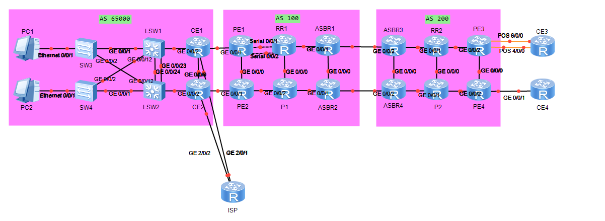
PE1-RR1的互联Serial接口,绑定为一个逻辑接口,成员链路采用HDLC,逻辑接口的IPv4地址、IPv6地址请按照图1、图5配置
PE3-CE3的互联POS接口,绑定为一个逻辑接口,成员链路采用PPP,逻辑接口的IPv4地址,请按照图1配置
# 1-----------------------------------------
#PE1
ipv6
int ip-trunk 1
    ipv6 enable
    ip addr 10.1.13.1 30
    ipv6 addr 2000:EAD8:99EF:CC3E:B2AD:9EFF:A2DD:1300 127
    q
int s0/0/1
    link-protocol hdlc
    ip-trunk 1
int s0/0/2
    link-protocol hdlc
    ip-trunk 1
    q

# RR1
ipv6
int ip-trunk 1
    ipv6 enable
    ip addr 10.1.13.2 30
    ipv6 addr 2000:EAD8:99EF:CC3E:B2AD:9EFF:A2DD:1301 127
    q
int s0/0/1
    link-protocol hdlc
    ip-trunk 1
int s0/0/2
    link-protocol hdlc
    ip-trunk 1
    q

# 测试-----------------------
# RR1
ping 10.1.13.1
ping ipv6 2000:EAD8:99EF:CC3E:B2AD:9EFF:A2DD:1300

# 2--------------------------------------------
# PE3
int mp-group 0/0/1
    dis cu conf vpn
    ip binding vpn-instance VPN1
    ip add 10.2.33.1 30
    q
int p4/0/0
    ppp mp mp-group 0/0/1
int p6/0/0
    ppp mp mp-group 0/0/1

# CE3
int mp-group 0/0/1
    ip add 10.2.33.2 30
    q
int p4/0/0
    ppp mp mp-group 0/0/1
int p6/0/0
    ppp mp mp-group 0/0/1

# 测试
# CE3
ping 10.2.33.1
2. IPv4 IGP~v0-IGP + v0-双点双向引入(2.3-5)~
2.1 基本配置
所有设备的接口IPv4地址按照图1配置(除PE1-RR1的逻辑接口外,已预配置)
Route-id与loopback0的IPv4地址相同。MPLS域各设备的loopback0为172.16.0.0/16的32位主机地址(已预配置),未来扩容的MPLS域各设备的loopback0,从172.16.0.0/16去可用的主机地址,比如172.16.1.21/32可能分布在AS100,也可能分布在AS200。
# 2---------------------------
# CE1
dis ip int br
router id 172.17.1.1
# CE2
dis ip int br
router id 172.17.1.2

# PE1
dis ip int br
router id 172.16.1.1
# PE2
dis ip int br
router id 172.16.1.20
# RR1
dis ip int br
router id 172.16.1.3
# P1
dis ip int br
router id 172.16.1.4
# ASBR1
dis ip int br
router id 172.16.1.5
# ASBR2
dis ip int br
router id 172.16.1.6

# ASBR3
dis ip int br
router id 172.16.1.7
# ASBR4
dis ip int br
router id 172.16.1.8
# RR2
dis ip int br
router id 172.16.1.9
# P2
dis ip int br
router id 172.16.1.10
# PE3
dis ip int br
router id 172.16.1.11
# PE4
dis ip int br
router id 172.16.1.2

# CE3
dis ip int br
router id 172.17.1.3
# CE4
dis ip int br
router id 172.17.1.4
2.2 OSPF
CE1和CE2之间的链路,及该两台设备的loopback0通告入OSPF区域0(已预配置)
CE1的g0/0/2.10和g0/0/2.20、CE2的g0/0/2.10和g0/0/2.20,直连网段通告入OSPF区域0,这些接口不能收发OSPF报文
RR2、P2、PE3、PE4在OSPF区域0中,cost如图2配置(已预配置)
PE3-PE4的OSPF链路类型为P2P
PE4上将loopback0地址引入OSPF。AS200中,各OSPF网元到PE4 loopback0的路由,要累加内部cost
# 1/2--------------------------------------
# CE1
int g0/0/2.10
    ospf enable 1 a 0
int g0/0/2.20
    ospf enable 1 a 0
dis ip int bri
ospf 1 router-id 172.17.1.1
    a 0
        network 172.17.1.1 0.0.0.0 # lo0
        network 10.2.12.1 0.0.0.0 # g0/0/0
        network 10.3.1.1 0.0.0.0 # g0/0/2的子接口10
        network 10.3.2.1 0.0.0.0 # g0/0/2的子接口20
        q
    silent-int g0/0/2.10
    silent-int g0/0/2.20

# CE2
int g0/0/2.10
    ospf enable 1 a 0
int g0/0/2.20
    ospf enable 1 a 0
dis ip int bri
ospf 1 router-id 172.17.1.2
    a 0
        network 172.17.1.2 0.0.0.0 # lo0
        network 10.2.12.2 0.0.0.0 # g0/0/0
        network 10.3.1.2 0.0.0.0 # g0/0/2的子接口10
        network 10.3.2.2 0.0.0.0 # g0/0/2的子接口20
        q
    silent-int g0/0/2.10
    silent-int g0/0/2.20

# 检查-------------------
# CE1/2
dis ospf peer bri
dis ospf int

# 3/4---------------------------
# RR2
dis ip int bri
ospf 1 router-id  172.16.1.9
    a 0
        network 172.16.1.9 0.0.0.0  # lo 0
        network 10.1.91.1 0.0.0.0 #g0/0/0
        network 10.1.119.1 0.0.0.0 #g0/0/2

# P2
dis ip int bri
ospf 1 router-id  172.16.1.10
    a 0
        network 172.16.1.10 0.0.0.0  # lo 0
        network 10.1.91.2 0.0.0.0 #g0/0/0
        network 10.1.102.1 0.0.0.0 #g0/0/2

# PE3
dis ip int bri
ospf 1 router-id  172.16.1.11
    a 0
        network 172.16.1.11 0.0.0.0  # lo 0
        network 10.1.112.1 0.0.0.0 #g0/0/0
        network 10.1.119.2 0.0.0.0 #g0/0/2

# PE4
dis ip int bri
ospf 1 router-id  172.16.1.2
    a 0    # 不能宣告lo0,原因为次优路径,涉及考点5
        network 10.1.112.2 0.0.0.0 #g0/0/0
        network 10.1.102.2 0.0.0.0 #g0/0/2

# 检查-----------------
# 所有设备
dis ospf int
dis ospf peer bri

# 4--------------------------------
# PE3
int g0/0/0
    ospf network-type p2p
# PE4
int g0/0/0
    ospf network-type p2p

# 检查-----------------
# 所有设备
dis ospf int
dis ospf peer bri

# 5-------------------------
# PE4
ip ip-prefix L0 permit 172.16.1.2 32
route-policy L0 permit node 10
    if-match ip-prefix L0
    apply tag 2  # 用于后面双向路由引入防止次优路径
ospf 1
    import-route direct type 1 route-policy L0

# 检查-----------------
# P2
dis ip rou 172.16.1.2 verbose  # 172.16.1.2的cost变为1501,tag为2
# RR2
dis ip rou 172.16.1.2 verbose  # 172.16.1.2的cost变为1511,tag为2
2.3 ISIS
AS100内loopback0和互联网接口全部开启ISIS协议,其中PE1、PE2的路由类型为L1,区域号为49.0001,RR1、P1路由类型为L12,区域号为49.0001,ASBR1、ASBR2路由类型为L2,区域号为49.0002。各网元system-id唯一,cost-style为wide,cost值如图2配置(除PE1-RR1之外的逻辑接口外,已预配置)
AS200内,RR2、P2、ASBR3、ASBR4的loopback0和互联接口全部开启isis协议,IS类型为L2,区域号为49.0003。各网元system-id唯一,cost-style为wide,cost值如图2配置(已预配置)
RR2-P2的ISIS链路类型为P2P
P1的ISIS进程,产生LSP的最大延迟时间是1S,初始延迟为50ms,递增时间为50ms。使能LSP的快速扩散特性。SPF计算间隔为1s,初始延迟为100ms,递增时间为100ms。
# 1/2----------------------
# PE1
dis cu conf isis # is-level level-1 # 如果有此配置,则不再进行配置
dis isis int
int loo 0  # 此处lo不能进入环回口,需要使用loo
    isis  enable
int ip-trunk 1
    dis th
    isis  enable
    isis cost 1500
dis isis int
dis isis peer # 2个

# PE2
dis cu conf isis # is-level level-1 # 如果有此配置,则不再进行配置
int loo 0  # 此处lo不能进入环回口,需要使用loo
    isis  enable
dis isis int
dis isis peer # 2个

# RR1
dis cu conf isis # is-level level-1-2 # 如果有此配置,则不再进行配置
dis isis int
int loo 0  # 此处lo不能进入环回口,需要使用loo
    isis  enable
int ip-trunk 1
    dis th
    isis  enable
    isis cost 1500
dis isis int
dis isis peer # 4个

# P1
dis cu conf isis # is-level level-1-2 # 如果有此配置,则不再进行配置
int loo 0  # 此处lo不能进入环回口,需要使用loo
    isis  enable
dis isis int
dis isis peer # 4个

# ASBR1
dis cu conf isis # is-level level-2 # 如果有此配置,则不再进行配置
int loo 0  # 此处lo不能进入环回口,需要使用loo
    isis  enable
dis isis int
dis isis peer # 2个

# ASBR2
dis cu conf isis # is-level level-2 # 如果有此配置,则不再进行配置
int loo 0  # 此处lo不能进入环回口,需要使用loo
    isis  enable
dis isis int
dis isis peer # 2个

# ASBR3
dis cu conf isis # is-level level-2 # 如果有此配置,则不再进行配置
int loo 0  # 此处lo不能进入环回口,需要使用loo
    isis  enable
dis isis int
dis isis peer # 2个

# ASBR4
dis cu conf isis # is-level level-2 # 如果有此配置,则不再进行配置
int loo 0  # 此处lo不能进入环回口,需要使用loo
    isis  enable
dis isis int
dis isis peer # 2个

# RR2
dis cu conf isis # is-level level-2 # 如果有此配置,则不再进行配置
int loo 0  # 此处lo不能进入环回口,需要使用loo
    isis  enable
dis isis int
dis isis peer # 2个

# P2
dis cu conf isis # is-level level-2 # 如果有此配置,则不再进行配置
int loo 0  # 此处lo不能进入环回口,需要使用loo
    isis  enable
dis isis int
dis isis peer # 2个


# 检查-----------------
# RR1
dis ip rou pro isis # 有1/20/4/5/6的路由
# ASBR3
dis ip rou pro isis # 有8/9/10的路由

# 3-----------------
# RR2
int g0/0/0
    isis circuit-type p2p
# P2
int g0/0/0
    isis circuit-type p2p
dis isis peer

# 4----------------------------
产生LSP的最大延迟时间是1S,初始延迟为50ms,递增时间为50ms。使能LSP的快速扩散特性。SPF计算间隔为1s,初始延迟为100ms,递增时间为100ms。
# P1
isis 1
    timer lsp-generation 1 50 50
    flash-flood
    timer spf 1 100 100
3. MPLS VPN~v0-BGP + V2-MPLS部分-1 + V2-MPLS部分-2~
CE1、CE2为VPN1的Hub-CE,PE1、PE2为Hub-CE,CE3、CE4为VPN1的spoke站点,PE3、PE4为SpokePE
CE4位Multi-VPN-instance CE,CE4的VPN实例VPN1,通过g0/0/1连接PE4CE4的OSPF需要做vrf-lite
合理设置VPN1参数,使得Spoke站点互访的数据必须经过Hub-CE设备,当CE1-PE1链路断开的情况下,PE1仍然可以学习到CE1的业务路由(PE3上VPN1的RD为100:13,ExportRT为100:1,ImportRT为200:1)
如图4,CE1通过g0/0/1.1和g0/0/1.2建立直连EBGP邻居接入PE1,CE1通过g0/0/1.2向PE1通告的BGP update中,某些路由的as path中有200。在CE1上,将OSPF路由导入BGP
如图4,CE2通过g0/0/1.1和g0/0/1.2建立直连EBGP邻居接入PE2,CE2通过g0/0/1.2向PE2通告的BGP update中,某些路由的as path中有200。在CE2上,将OSPF路由导入BGP
CE3通过OSPF区域1接入PE3通过PE3-CE3的逻辑接口互通,通告CE3的各环回口;CE4通过OSPF区域0接入PE4,通过PE4-CE4的g0/0/1.1接口互通,通告CE4的各环回口
如图3,AS100、AS200内各网元配置MPLS LSR ID,全局使能MPLS,MPLS LDP(已预配置)。AS100、AS200内各直连链路建立LDP邻居。(除PE1-RR1之外的逻辑链路外,已预配置)
ASBR1-ASBR3,ASBR2-ASBR4之间通过直连接口建立BGP邻居关系。在ASBR上,在ASBR上,将ISIS的loopback0路由引入BGP。假设AS100和AS200中的loopback0地址为172.16.A.Y/32。当Y为奇数时,对端设备访问本AS设备的loopback0,优选ASBR1-ASBR3;当Y为偶数时,对端设备访问本AS设备的loopback0,优选ASBR2-ASBR4.保证配有有最好的扩展性
在RR2、P2上,ISIS和OSPF双向引入前缀为172.16.0.0/16的主机路由。被引入的协议的cost要继承到引入后的协议中,P2和PE4的loopback0互访走最优路径。配置要求有最好的扩展性
如图4,各站点通过MPLS BGP VPN 跨域 Option C 方案二,能够相互学习路由。PE1-RR1、PE2-RR1、PE3-RR2、PE4-RR2之间建立MP-IBGP连接的源接口为loopback0。RR1-RR2之间建立MP-EBGP邻居的源接口为loopback0。
在CE1、CE2上配置EBGP的协议优先级为120
在CE1、CE2上面,将BGP导入OSPF。保证配置有最好的扩展性(和4、5要求重合)
在PE3、PE4上修改BGP local preference属性。实现CE3、CE4访问直连的10.3.x.0/24网段时,若x为奇数,PE3、PE4优选下一跳为PE1,若x为偶数,PE3、PE4优选下一跳为PE2,不用考虑来回路径是否一致
# 3--------------------------
#PE1
dis cu conf vpn
ip vpn-instance HUB
    vpn-target 200:1 export
    q
ip vpn-instance VPN1
    vpn-target 100:1 200:1 import # 200:1的作用:当CE1-PE1链路断开的情况下,PE1仍然可以学习到CE1的业务路由
dis cu int# 查看intg0/0/1.1和g0/0/1.2分别绑定VPN1和HUB,并且都已经配置arp broadcast enable

#PE2
dis cu conf vpn
ip vpn-instance HUB
    vpn-target 200:1 export
    q
ip vpn-instance VPN1
    vpn-target 100:1 200:1 import
dis cu int# 查看intg0/0/1.1和g0/0/1.2分别绑定VPN1和HUB,并且都已经配置arp broadcast enable

# PE3
ip vpn-instance VPN1
    vpn-target 100:1 export
    vpn-target 200:1 import

# PE4
ip vpn-instance VPN1
    vpn-target 100:1 export
    vpn-target 200:1 import

# 4/5----------------------
#CE1
dis ip int bri
bgp  65000
    router-id 172.17.1.1
    peer 10.2.11.2 as 100
    peer 10.2.11.6 as 100
    import ospf 1

#PE1
bgp 100
    dis ip int bri
    router-id 172.16.1.1
    ipv4-family vpn-instance VPN1
        peer 10.2.11.1 as 65000
    ipv4-family vpn-instance HUB
        peer 10.2.11.5 as 65000
        peer 10.2.11.5 allow-as-loop

#CE2
dis ip int bri
bgp  65000
    router-id 172.17.1.2
    peer 10.2.22.2 as 100
    peer 10.2.22.6 as 100
    import ospf 1

#PE2
bgp 100
    dis ip int bri
    router-id 172.16.1.20
    ipv4-family vpn-instance VPN1
        peer 10.2.22.1 as 65000
    ipv4-family vpn-instance HUB
        peer 10.2.22.5 as 65000
        peer 10.2.22.5 allow-as-loop

# 检查-----------------
# 所有设备
dis bgp vpnv4 all peer


# 6/2--------------------------
# PE3
ospf 2 vpn-instance VPN1
    a 1
        dis ip int bri # 查看MP口
        network 10.2.33.1 0.0.0.0
# CE3
dis ip int bri
ospf 1 router-id 172.17.1.3
    area 1 # 同时需要宣告所有环回口
        net 10.2.33.2 0.0.0.0
        net 172.17.1.3 0.0.0.0
        net 10.3.3.3 0.0.0.0
dis ospf peer bri

# PE4
ospf 2 vpn-instance VPN1
    a 0
        dis ip int bri # 查看g0/0/1口
        net 10.2.44.1 0.0.0.0
# CE4
dis cu int  # 配置地址的3个接口都需要绑定VPN1
dis ip int bri
ospf 1 vpn-instance VPN1
    area 0 # 同时需要宣告所有环回口
        net 10.2.44.2 0.0.0.0
        net 172.17.1.4 0.0.0.0
        net 10.4.4.4 0.0.0.0
        q
    vpn-instance-capability simple
dis ospf peer bri

# 7.2 BGP------------------此部分最好在记事本中写好配置
# PE1/PE2/P1/ASBR1/ASBR2
bgp 100
    router-id 172.16.1.1/20/4/5/6
    peer 172.16.1.3 as 100
    peer 172.16.1.3 connect lo 0
# RR1
bgp 100
    router-id 172.16.1.3
    peer 172.16.1.1 as 100 # 配置邻居
    peer 172.16.1.20 as 100
    peer 172.16.1.4 as 100
    peer 172.16.1.5 as 100
    peer 172.16.1.6 as 100
    dis th
    peer 172.16.1.1 co lo 0 # 配置更新源
    peer 172.16.1.20 co lo 0
    peer 172.16.1.4 co lo 0
    peer 172.16.1.5 co lo 0
    peer 172.16.1.6 co lo 0
    peer 172.16.1.1 re # 配置反射器
    peer 172.16.1.20 re
    peer 172.16.1.4 re
    peer 172.16.1.5 re
    peer 172.16.1.6 re

# ASBR1
bgp 100
    dis th
    peer 172.16.1.3 next-hop-local
    peer 10.1.57.2  as 200

# ASBR2
bgp 100
    dis th
    peer 172.16.1.3 next-hop-local
    peer 10.1.68.2 as 200

# ASBR3
bgp 200
    router-id 172.16.1.7
    peer 10.1.57.1  as 100
    peer 172.16.1.9 as 200
    peer 172.16.1.9 co lo 0
    peer 172.16.1.9 next-hop-local

# ASBR4
bgp 200
    router-id 172.16.1.8
    peer 10.1.68.1 as 100
    peer 172.16.1.9 as 200
    peer 172.16.1.9 co lo 0
    peer 172.16.1.9 next-hop-local

# P2/PE3/PE4
bgp 200
    router-id 172.16.1.10/11/2
    peer 172.16.1.9 as 200
    peer 172.16.1.9 co lo 0

# RR2
bgp 200
    router-id 172.16.1.9
    peer 172.16.1.7 as 200 # 配置邻居
    peer 172.16.1.8 as 200
    peer 172.16.1.10 as 200
    peer 172.16.1.11 as 200
    peer 172.16.1.2 as 200
	peer 172.16.1.7 co lo 0 # 更新源
    peer 172.16.1.8 co lo 0
    peer 172.16.1.10 co lo 0
    peer 172.16.1.11 co lo 0
    peer 172.16.1.2 co lo 0
	peer 172.16.1.7 re # 反射器
    peer 172.16.1.8 re
    peer 172.16.1.10 re
    peer 172.16.1.11 re
    peer 172.16.1.2 re

# 检查-----------------
# RR1/2
dis bgp peer  # 5个邻居建立
# ASBR1/2/3/4
dis bgp peer # 2个邻居

# 7.1 MPLS--------------------
# AS100和AS200内所有设备
mpls lsr-id 172.16.1.1/20/3/4/5/6/7/8/9/10/11/2
mpls
mpls ldp
# AS100和AS200内所有设备的互联接口全部开启mpls ldp,将需要开启mpls接口的配置写入记事本,然后在相应设备上粘贴配置
# PE1
int ip 1
    mpls
    mpls ldp
int g0/0/0
    mpls
    mpls ldp
# PE2
int g0/0/0
    mpls
    mpls ldp
int g0/0/2
    mpls
    mpls ldp
# RR1
int ip 1
    mpls
    mpls ldp
int g0/0/0
    mpls
    mpls ldp
int g0/0/1
    mpls
    mpls ldp
# P1
int g0/0/0
    mpls
    mpls ldp
int g0/0/1
    mpls
    mpls ldp
int g0/0/2
    mpls
    mpls ldp
# ASBR1:注意这是option C方案,AS之间的接口不能配置
int g0/0/0
    mpls
    mpls ldp
int g0/0/1
    mpls
    mpls ldp
# ASBR2
int g0/0/0
    mpls
    mpls ldp
int g0/0/1
    mpls
    mpls ldp
# ASBR3
int g0/0/0
    mpls
    mpls ldp
int g0/0/1
    mpls
    mpls ldp
# ASBR4
int g0/0/0
    mpls
    mpls ldp
int g0/0/1
    mpls
    mpls ldp
#RR2
int g0/0/0
    mpls
    mpls ldp
int g0/0/1
    mpls
    mpls ldp
int g0/0/2
    mpls
    mpls ldp
#P2
int g0/0/0
    mpls
    mpls ldp
int g0/0/1
    mpls
    mpls ldp
int g0/0/2
    mpls
    mpls ldp
#PE3
int g0/0/0
    mpls
    mpls ldp
int g0/0/2
    mpls
    mpls ldp
#PE4
int g0/0/0
    mpls
    mpls ldp
int g0/0/2
    mpls
    mpls ldp

# 检查-----------------
# AS100/200内所有设备
dis mpls ldp peer

# 8-----------------------
# ASBR1
acl 2000   # 4台ASBR的ACL都是相同的,建议复制,不同的是route-policy
    rule permit source 172.16.1.0 0.0.0.254
acl 2001
    rule permit source 172.16.1.1 0.0.0.254
route-policy AB permit node 10
    if-match acl 2000
    apply cost 200
route-policy AB permit node 20
    if-match acl 2001
    apply cost 100
bgp 100
    import-route isis 1 route-policy AB
# ASBR3
acl 2000
    rule permit source 172.16.1.0 0.0.0.254
acl 2001
    rule permit source 172.16.1.1 0.0.0.254
route-policy AB permit node 10
    if-match acl 2000
    apply cost 200
route-policy AB permit node 20
    if-match acl 2001
    apply cost 100
bgp 200
    import-route isis 1 route-policy AB


# ASBR2
acl 2000
    rule permit source 172.16.1.0 0.0.0.254
acl 2001
    rule permit source 172.16.1.1 0.0.0.254
route-policy AB permit node 10
    if-match acl 2000
    apply cost 100
route-policy AB permit node 20
    if-match acl 2001
    apply cost 200
bgp 100
    import-route isis 1 route-policy AB
# ASBR4
acl 2000
    rule permit source 172.16.1.0 0.0.0.254
acl 2001
    rule permit source 172.16.1.1 0.0.0.254
route-policy AB permit node 10
    if-match acl 2000
    apply cost 100
route-policy AB permit node 20
    if-match acl 2001
    apply cost 200
bgp 200
    import-route isis 1 route-policy AB

# 检查-----------------
# 4台ASBR
dis bgp rou # 奇数路由走1/3,反之亦然。例如ASBR1上172.16.1.1的下一跳0.0.0.0(默认为ASBR3),172.16.1.2的下一跳就是172.16.1.6


# 9--------------------
## RR2
ip ip-prefix 172 permit 172.16.0.0 16 greater-equal 32  # 匹配172的主机路由

route-policy O2I deny node 10
    if-match tag 100
route-policy O2I permit node 20
    if-match ip-prefix 172
    apply tag 200
route-policy I2O deny node 10
    if-match tag 101
route-policy I2O permit node 20
    if-match ip-prefix 172
    apply tag 201

route-policy OASE permit node 10
    if-match tag 2 # 与PE4引入时指定的tag一致
    apply preference 14   # 针对PE4引入的ospf外部路由设置优先级为14(ospf为10,isis为15)
ospf 1
    import-route isis 1 type 1 route-policy I2O
    preference ase route-policy OASE
isis 1
    import-route ospf 1 inherit-cost route-policy O2I

dis route-policy  # 此时查看匹配到的路由是不是有0,因为路由之前已经过去了,需要把deny重新配置一下
dis cu conf routr-policy
undo route-policy O2I node 10
route-policy O2I deny node 10
    if-match tag 300
undo route-policy I2O node 10
route-policy I2O deny node 10
    if-match tag 201


# P2
ip ip-prefix 172 permit 172.16.0.0 16 greater-equal 32

route-policy I2O permit node 20
    if-match ip-prefix 172
    apply tag 100
route-policy I2O deny node 10
    if-match tag 200
route-policy O2I permit node 20
    if-match ip-prefix 172
    apply tag 101
route-policy O2I deny node 10
    if-match tag 201
route-policy OASE permit node 10
    if-match tag 2 # 与PE4引入时指定的tag一致
    apply preference 14   # 针对PE4引入的ospf外部路由设置优先级为14(ospf为10,isis为15)
ospf 1
    import-route isis 1 type 1 route-policy I2O
    preference ase route-policy OASE
isis 1
    import-route ospf 1 inherit-cost route-policy O2I

dis route-policy  # 此时查看匹配到的路由是不是有0,因为路由之前已经过去了,需要把deny重新配置一下
dis cu conf routr-policy
undo route-policy O2I node 10
route-policy O2I deny node 10
    if-match tag 301
undo route-policy I2O node 10
route-policy I2O deny node 10
    if-match tag 200

# 检查-----------------
# RR2/P2
dis route-policy  # 此时匹配的路由条数不应该有0
# P2
dis ip rou # 到达PE4(172.16.1.2)的路由应该为O_ASE,接口为g0/0/2,即OSPF的外部路由而不是ISIS的路由
# PE4
dis ip rou pro ospf # 到达P2(172.16.1.10)为g0/0/2接口


# 10-------------------------
# ASBR1/2/3/4
int g0/0/2  # ASBR互联接口开启mpls
    mpls
    q
route-policy MPLS permit no 10 # 向ebgp邻居通告路由时带标签
    apply mpls-label
ip ip-prefix 172 permit 172.16.0.0 16 great 32 #将对端172的主机路由引入本AS内部IGP
route-policy 172 permit node 10
    if-match ip-prefix 172
    apply tag 1234
route-policy AB deny node 5  # 防止将BGP引入IGP时出环
    if-match tag 1234
isis   # IGP引入BGP的路由
    import-route bgp inherit-cost route-policy 172
mpls
    lsp-trigger bgp-label-route ip-prefix 172  # 让LDP为来自BGP的带标签的路由分配IGP标签

# ASBR1
bgp 100
    peer 10.1.57.2 route-policy MPLS export
    peer 10.1.57.2 label-route-capability  # 针对邻居开启公网路由带标签能力
    preference 12 255 255  # 修改bgp优先级,保证IGP优选。ebgp的优先级12小于ISIS的优先级15,优选bgp;ibgp的优先级255大于ISIS的优先级,优选ISIS;本地优先级为255
# ASBR3
bgp 200
    peer 10.1.57.1 route-policy MPLS export
    peer 10.1.57.1 label-route-capability
    preference 12 255 255
# ASBR2
bgp 100
    peer 10.1.68.2 route-policy MPLS export
    peer 10.1.68.2 label-route-capability
    preference 12 255 255
# ASBR4
bgp 200
    peer 10.1.68.1 route-policy MPLS export
    peer 10.1.68.1  label-route-capability
    preference 12 255 255

# PE1/2
bgp 100
    ipv4-family vpnv4
        peer 172.16.1.3 enable
# RR1
bgp 100
    peer 172.16.1.9 as 200
    peer 172.16.1.9 co lo 0
    peer 172.16.1.9 ebgp-max-hop
    ipv4-family unicast
        undo peer 172.16.1.9 enable  # 关闭RR之间的ipv4邻居,防止路由选路错误
    ipv4-family vpnv4
        undo policy vpn-target
        peer 172.16.1.9 enable
        peer 172.16.1.9 next-hop-invariable
        peer 172.16.1.9 allow-as-loop
        peer 172.16.1.1 enable
        peer 172.16.1.1 re
        peer 172.16.1.1 next-hop-invariable # 不修改下一跳
        peer 172.16.1.20 enable
        peer 172.16.1.20 re
        peer 172.16.1.20 next-hop-in
# PE3/4
bgp 200
    ipv4-family vpnv4
        peer 172.16.1.9 enable
    ipv4-family vpn-instance VPN1   # 边缘设备路由的双向引入,使CE3/4学到相应的路由
        import ospf 2
ospf 2
    import bgp type 1

# RR1/P1:配置isis的路由泄露
ip ip-prefix 172 permit 172.16.0.0 16 gr 32
isis 1
    import isis level-2 into level-1 filter-policy ip-prefix 172

# RR2
bgp 200
    peer 172.16.1.3 as 100
    peer 172.16.1.3 co lo 0
    peer 172.16.1.3 ebgp-max-hop
    ipv4-family unicast
        undo peer 172.16.1.9 enable
    ipv4-family vpnv4
        undo policy vpn-target
        peer 172.16.1.3 enable
        peer 172.16.1.3 next-hop-in
        peer 172.16.1.3 allow-as-loop
        peer 172.16.1.11 enable
        peer 172.16.1.11 re
        peer 172.16.1.11 next-hop-in
        peer 172.16.1.2 enable
        peer 172.16.1.2 re
        peer 172.16.1.2 next-hop-in

# 检查-----------------
# RR1/2
dis bgp vpnv4 all peer #各有3个邻居
dis bgp peer # 查看两个RR之间的邻居
# RR2/PE3/PE4
dis bgp vpnv4 all rou  # 是否学到CE1/2/3/4上的路由10.3.1.0、10.3.2.0、10.3.3.3、10.4.4.4
# RR1/PE1/PE2
dis bgp vpnv4 all rou  # 是否学到CE1/2/3/4上的路由10.3.1.0、10.3.2.0、10.3.3.3、10.4.4.4
# RR1/P1
dis ip rou pro isis  # 查看时候学习到isis level2的路由,主要是192.168.1.11/2

# 11/12--------------------------
# CE1/2:修改eBGP的优先级
bgp 65000
    preference 120 255 255
ospf 1
    import bgp type 1  # 引入之前先做PE1/2上面的soo
# PE1:为了防环,需要配置soo属性
bgp 100
    ipv4-family vpn-instance HUB
        peer 10.2.11.5 soo 100:12
    ipv4-family vpn-instance VPN1
        peer 10.2.11.1 soo 100:12
# PE2:为了防环,需要配置Soo属性
bgp 100
    ipv4-family vpn-instance HUB
        peer 10.2.22.5 soo 100:12
    ipv4-family vpn-instance VPN1
        peer 10.2.22.1 soo 100:12

# 13------------------
# PE3/4
acl 2000
    rule permit source 10.3.0.0 0.0.254.0
acl 2001
    rule permit source 10.3.1.0 0.0.254.0
ip ip-prefix NH-PE1 permit 172.16.1.1 32
ip ip-prefix NH-PE2 permit 172.16.1.20 32
route-policy AB permit node 10
    if-match acl 2000
    if-match ip next-hop ip-prefix NH-PE2
    apply local-preference 200   # 本地优先级越大越优,cost越小越优
route-policy AB permit node 20
    if-match acl 2001
    if-match ip next-hop ip-prefix NH-PE1
    apply local-preference 200
route-policy AB permit node 30  # 放行其他路由
bgp 200
    ipv4-family vpnv4
    peer 172.16.1.9 route-policy AB import  # 从反射器来的路由应用上面的条件

# 检查-----------------
# PE3/4
dis bgp vpnv4 all rou #10.3.1.0下一跳为172.16.1.1,本地优先级为200;10.3.2.0下一条为172.16.1.20,本地优先级为200

# 整个大题最后的测试
# CE3/4
tracert -a 10.3.3.3 10.4.4.4 # CE4:9hop
tracert -a 10.3.3.3 10.3.1.10 # PC1:8hop
tracert -a 10.3.3.3 10.3.2.20 # PC2:8hop

# CE4
tracert -vpn-instance VPN1 -a 10.4.4.4 10.3.3.3  # CE3:9hop
tracert -vpn-instance VPN1 -a 10.4.4.4 10.3.1.10 # PC1:8hop
tracert -vpn-instance VPN1 -a 10.4.4.4 10.3.2.20 # PC2:8hop

# PC1/2
tracert 10.3.3.3 # 3hop
tracert 10.4.4.4

# PC1
tracert 10.3.2.20 # 2hop
# PC2
tracert 10.3.1.10 # 2hop
4. FeatureV0-feature
4.1 HA
CE1配置静态的默认路由访问ISP,下一跳IP为100.0.1.2.该默认路由要与CE1-ISP链路的BFD状态绑定(CE1的对端设备不支持BFD),感知故障的时间要小于150ms
CE2配置静态的默认路由访问ISP,下一跳IP为200.0.2.2.该默认路由要与CE2-ISP链路的NQA ICMP测试绑定,间隔5S测试执行1次
CE3、CE4能够通过默认路由访问ISP。CE1-ISP的链路断开时,CE1仍能访问ISP;CE2-ISP的链路断开时,CE2仍能访问ISP
# 1---------------------------
# ISP
int g2/0/1
    ip addr 100.0.1.2 30

# CE1
int g2/0/1
    ip addr 100.0.1.1 30
bfd # 开启全局bfd
    q
bfd huawei bind peer-ip 100.0.1.2 int g2/0/1 one-arm-echo
    discriminator local 1  # 配置本地设备标示为1
    min-echo-rx-interval 40 # 40的3倍小于150
    commit
    q
ip route-static 0.0.0.0 0.0.0.0 100.0.1.2 track bfd-session huawei
# 检测---------
dis bfd session all

# 2---------------------------
# ISP
int g2/0/2
    ip addr 200.0.2.2 30

# CE2
int g2/0/2
    ip addr 200.0.2.1 30
    q
nqa test-instance huawei huawei
    test-type icmp
    destination-address ipv4 200.0.2.2
    frequency 5
    start now
    q
ip route-static 0.0.0.0 0.0.0.0 200.0.2.2 track nqa huawei huawei
# 检测---------
dis nqa history

# 3--------------
# 使用ospf结合bgp下发默认
# CE1/2
ospf 1
    default-route-advertise
bgp 65000
    network 0.0.0.0
# PE3/4
ospf 2
    default-route-advertise
# 检测--------
# CE3
dis ip rou   # 查看是否有默认路由
# CE4
dis ip rou vpn-instance VPN1 # 查看是否有默认路由
4.2 NAT
在CE1上,10.3.0.0/16(不含10.3.2.10)的内网地址转换为102.0.1.2-102.0.1.6,通过g2/0/1访问ISP。
#  CE1
acl 2999
    rule deny source 10.3.2.10 0
    rule permit source 10.3.0.0 0.0.255.255
nat address-group 1 102.0.1.2 102.0.1.6
int g2/0/1
    nat outbound 2999 address-group 1
    nat server protocol tcp global 102.0.1.1 www inside 10.3.2.10 www
    nat server protocol tcp global 102.0.1.1 ftp inside 10.3.2.10 ftp
#  CE2
acl 2999
    rule deny source 10.3.2.10 0
    rule permit source 10.3.0.0 0.0.255.255
nat address-group 1 102.0.1.2 102.0.1.6
int g2/0/2
    nat outbound 2999 address-group 1
    nat server protocol tcp global 102.0.1.1 www inside 10.3.2.10 www
    nat server protocol tcp global 102.0.1.1 ftp inside 10.3.2.10 ftp
4.3 Qos
在CE1的g2/0/1、CE2的g2/0/2的出方向,周一至周五的8:00-18:00,对TCP目的端口号为6881-6999的流量,承诺的平均速率为1Mbps
# 1/2/3--------------
# CE1
time-range WORKING 8:00 to 18:00 working-day
acl 3000
    rule permit tcp desination-port range 6881 6999 timer-range WORKING
traffic classifiter HUAWEI operator or
    if-match acl 3000
traffic behavior HUAWEI
    car cir 1000
traffic policy HUAWEI
    classifier HUAWEI behavior HUAWEI
interface g2/0/1
    traffic-policy HUAWEI outbound
# CE2
time-range WORKING 8:00 to 18:00 working-day
acl 3000
    rule permit tcp desination-port range 6881 6999 timer-range WORKING
traffic classifiter HUAWEI
    if-match acl 3000
traffic behavior HUAWEI
    car cir 1000
traffic policy HUAWEI
    classifier HUAWEI behavior HUAWEI
interface g2/0/2
    traffic-policy HUAWEI outbound

# 检查-----
dis traffic policy user-defied
5. IPv6
5.1 基本配置
所有相关设备接口的IPv6地址,按照图6配置(除PE1-RR1的逻辑接口外,已预配置)在WAN那道题中已经配置
5.2 IPv6 ISIS
如图6,PE1、PE2、RR1、P1、ASBR1、ASBR2运行isis协议,各直连网段通告入isis,配置各链路cost
# PE1
ipv6
isis
    ipv6 enable topology ipv6
int loo 0
    isis ipv6 enable
int ip 1
    isis ipv6 enable
    isis ipv6 cost 1550
int g0/0/0
    isis ipv6 enable
    isis ipv6 cost 20

# PE2
ipv6
isis
    ipv6 enable topology ipv6
int loo 0
    isis ipv6 enable
int g0/0/0
    isis ipv6 enable
    isis ipv6 cost 20
int g0/0/2
    isis ipv6 enable
    isis ipv6 cost 1500

# RR1
ipv6
isis
    ipv6 enable topology ipv6
int loo 0
    isis ipv6 enable
int ip 1
    isis ipv6 enable
    isis ipv6 cost 1550
int g0/0/0
    isis ipv6 enable
    isis ipv6 cost 80
int g0/0/1
    isis ipv6 enable
    isis ipv6 cost 860

# P1
ipv6
isis
    ipv6 enable topology ipv6
int loo 0
    isis ipv6 enable
int g0/0/2
    isis ipv6 enable
    isis ipv6 cost 1500
int g0/0/0
    isis ipv6 enable
    isis ipv6 cost 80
int g0/0/1
    isis ipv6 enable
    isis ipv6 cost 1000

# ASBR1
ipv6
isis
    ipv6 enable topology ipv6
int loo 0
    isis ipv6 enable
int g0/0/1
    isis ipv6 enable
    isis ipv6 cost 860
int g0/0/0
    isis ipv6 enable
    isis ipv6 cost 100

# ASBR2
ipv6
isis
    ipv6 enable topology ipv6
int loo 0
    isis ipv6 enable
int g0/0/1
    isis ipv6 enable
    isis ipv6 cost 1000
int g0/0/0
    isis ipv6 enable
    isis ipv6 cost 100

# 检查---------
dis ipv6 rou pro isis # 可以查看到AS100内所有其他设备环回口路由,建议在PE2上查看
5.3 IPv6 Multicast
如图7,AS100中,相邻设备建立PIM IPv6 SM的邻居关系。PE1的e0/0/0静态加入组FF1E::AA
ASBR1的loopback0、ASBR2的loopback0为C-BSR且都为FF1E::/112的C-RP。ASBR1的loopback0成为BSR,ASBR2的loopback0成为FF1E::/112的RP
无论哪个C-RP成为RP,都要确保PIM IPv6域生成(*,G)表项无次优路径
# 1------------------------
# RR1/P1
isis 1
    ipv6 import-route isis level-2 into level-1    # 路由渗透,保证AS内环回口互通,可以做与v1相同的策略进行防环,此处不做了

# PE1
multicast ipv6 routing-enabel
int g0/0/0
    pim ipv6 sm  # 先开启
    pim ipv6 silent  # 保障安全
    mld enable   # 后开启
    mld static-group FF1E::AA  # 静态加组
int loo 0
    pim ipv6 sm
int ip 1
    pim ipv6 sm

# PE2
int loo 0
    pim ipv6 sm
int g0/0/0
    pim ipv6 sm
int g0/0/2
    pim ipv6 sm

# RR1
int ip 1
    pim ipv6 sm
int g0/0/0
    pim ipv6 sm
int g0/0/1
    pim ipv6 sm

# P1
int g0/0/0
    pim ipv6 sm
int g0/0/1
    pim ipv6 sm
int g0/0/2
    pim ipv6 sm

# ASBR1
int g0/0/0
    pim ipv6 sm
int g0/0/1
    pim ipv6 sm

# ASBR2
int g0/0/0
    pim ipv6 sm
int g0/0/2
    pim ipv6 sm

# 2--------------------
# ASBR1/ASBR2
acl ipv6 2000
    rule permit source FF1E::AA/112  # 定义RP的服务组范围
acl ipv6 3100
    rule permit ipv6 source 2000:EAD8:99EF:CC3E:B2AD:9EFF:A2DD:DCA5/128 destination FF1E::AA/112
    rule permit ipv6 source 2000:EAD8:99EF:CC3E:B2AD:9EFF:A2DD:DCA6 128 destination FF1E::AA/112

# ASBR1
pim-ipv6
    c-bsr priority 200
    c-bsr 2000:EAD8:99EF:CC3E:B2AD:9EFF:A2DD:DCA5
    c-rp 2000:EAD8:99EF:CC3E:B2AD:9EFF:A2DD:DCA5 group-po 2000 pri 200
    crp-policy 3100
# ASBR2
pim-ipv6
    c-bsr priority 100
    c-bsr 2000:EAD8:99EF:CC3E:B2AD:9EFF:A2DD:DCA6
    c-rp 2000:EAD8:99EF:CC3E:B2AD:9EFF:A2DD:DCA6 group-po 2000 pri 100
    crp-policy 3100
# 检查--------------
# PE1
dis pim ipv6 bsr-info  # BSR地址为xxxxxxDCA5,优先级为200,C-RP数量2个
dis pim ipv6 rp-info  # RP地址为xxxxxxDCA5,优先级为200;下一个RP地址为xxxxxxDCA6,优先级为100

# 3------------------
# PE1
pim-ipv6
    spt-switch-threshold infinity
# 检查--------------
#ASBR1/2
dis pim ipv6 rou  # 只有(*,FF1E::AA)