企业网实践拓扑
规划说明
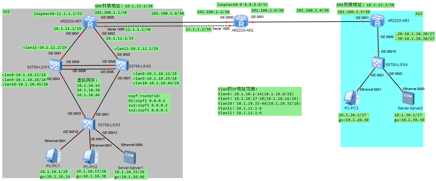
AS1(包含R1、SW1、SW2、SW3)为企业主园区网络,AS2为企业分支网络,云部分代表互联网设备8.8.8.8。完成AS1和AS2基本的网络功能,可以访问互联网8.8.8.8以及通过GRE VPN使得位于两个AS的终端实现跨广域网的通信。
架构设计
- AS1中,R1作为企业网关出口,负责接入互联网8.8.8.8,以及和R3的VPN互联,同事作为AS1内部的核心路由器。
- SW1和SW2作为AS1的汇聚层交换机,其上的Vlanif接口如路由拓扑所示,SW3作为接入层的交换机。
- AS2中,R3作为该分支网络的网关出口,SW4作为接入2层交换机,连接终端和路由器。
- 在两个AS中,每个AS最多出现一条静态路由。
配置
交换网络部分
VLAN的规划和接入
| 交换机接口 | 所属VLAN |
|---|---|
| sw1-g0/0/1 | vlan11 |
| sw2-g0/0/2 | vlan12 |
| sw3-g0/0/10 | vlan8 |
| sw3-g0/0/11 | vlan9 |
| sw3-g0/0/12 | vlan10 |
| sw4-g0/0/1 | vlan20 |
| sw4-g0/0/2 | vlan30 |
- 在AS1中的交换机上创建VLAN8/9/10/11/12/99
- 在AS2中的交换机上创建VLAN20/30
- 按照表中将接口划入vlan
# sw1
vlan batch 8 9 10 11 12 99
int g0/0/1
port link-type access
port default vlan 11
# sw2
vlan batch 8 9 10 11 12 99
int g0/0/2
port link-type access
port default vlan 12
# sw3
vlan batch 8 9 10 11 12 99
int g0/0/10
port link-type access
port default vlan 8
int g0/0/11
port link-type access
port default vlan 9
int g0/0/12
port link-type access
port default vlan 10
# sw4
vlan batch 20 30
int g0/0/1
port link-type access
port default vlan 20
int g0/0/2
port link-type access
port default vlan 30
实施Trunk封装
- AS1内交换机的互联接口实施标准封装格式的Trunk链路
- AS1内所有Trunk上允许除了VLAN1之外的所有VLAN通过,且所有VLAN的流量必须携带Tag
- AS2内的交换机上实施Trunk,安全起见仅仅允许对应的VLAN通过
# sw1
int g0/0/3
port link-type trunk
port trunk allow-pass vlan all
undo port trunk allow-pass vlan 1
int g0/0/5
port link-type trunk
port trunk allow-pass vlan all
undo port trunk allow-pass vlan 1
int g0/0/6
port link-type trunk
port trunk allow-pass vlan all
undo port trunk allow-pass vlan 1
# sw2
int g0/0/1
port link-type trunk
port trunk allow-pass vlan all
undo port trunk allow-pass vlan 1
int g0/0/5
port link-type trunk
port trunk allow-pass vlan all
undo port trunk allow-pass vlan 1
int g0/0/6
port link-type trunk
port trunk allow-pass vlan all
undo port trunk allow-pass vlan 1
# sw3
int g0/0/1
port link-type trunk
port trunk allow-pass vlan all
undo port trunk allow-pass vlan 1
int g0/0/3
port link-type trunk
port trunk allow-pass vlan all
undo port trunk allow-pass vlan 1
#sw4
int g0/0/10
port link-type trunk
port trunk allow-pass vlan 20 30
实施生成树协议STP
- AS1和AS2内实施802.1s(MSTP)的生成树(华为设备默认为MSTP)
- sw1在实例(instance)1中具有成为vlan8/10/11的根的最大的可能性,同时sw1是其他vlan(9/12/99)的备份根
- sw2反之,即成为vlan8/10/11的备份根,成为其他vlan(9/12/99)的主根
- 区域名为ender,修订版本号为1
- sw1/2/3上,仅使用一条命令,使得连接终端的接口可以快速进入转发状态
- sw4的接口下配置命令,使得连接其他设备的接口快速进入转发状态
- 为了保护交换网络,在接入层交换机(sw3/4)上,一旦收到非法的BPDU则关闭接口
实例instance,即将多个vlan绑定成一个组
# sw1\sw2\sw3
stp region-configuration
region-name ender
revision-level 1
instance 1 vlan 8 10 11
instance 2 vlan 9 12 99
active region-configuration
# sw1
stp instance 1 priority 0  # 或者stp instance 1 root primary
stp instance 2 root secondary
# sw2
stp instance 1 root secondary
stp instance 2 root primary
# sw1\sw2\sw3
stp edged-port default
# sw4
int g0/0/1
stp edged-port enable
int g0/0/2
stp edged-port enable
int g0/0/10 #此接口如果不配置边缘端口,出现断网等情况,还会经过Listen等状态,导致恢复过慢
stp edged-port enable
# sw4
stp bpdu-protection
# sw3,需要将上连接口的边缘端口关闭
stp bpdu-protection
int g0/0/1
stp edged-port disable
shutdown
undo shutdown
int g0/0/3
stp edged-port disable
shutdown
undo shutdown
实施以太链路聚合
- 为了保证汇聚交换机之间拥有足够的带宽,在汇聚交换机之间实施手工模式(华为默认此模式)的以太链路聚合
- 以太链路聚合使用基于源目IP的负载分担方式(华为默认此方式)
# sw1/sw2
clear configuration int g0/0/5
y
clear configuration int g0/0/6
y
int eth-trunk 12
trunkport g 0/0/5 to 0/0/6
port link-type trunk
port trunk allow vlan all
undo port trunk allow vlan 1
int g0/0/5
un shut
int g0/0/6
un shut
2层网络向3层网络过渡
- 在所有路由器上配置IP地址,保证路由器之间、路由器和交换机之间的直连IP地址通信
- 在所有交换机上配置IP地址,保证路由器之间、路由器和交换机之间的直连IP地址通信
# R1
int g0/0/0
ip addr 202.100.1.1 30
int g0/0/1
ip addr 10.1.11.1 29
int g0/0/2
ip addr 10.1.12.1 29
int s1/0/0
ip addr 12.1.1.1 30
# R2
int g0/0/0
ip addr 202.100.1.2 30
int g0/0/1
ip addr 202.100.1.6 30
int s1/0/0
ip addr 12.1.1.2 30
# R3
int g0/0/1
ip addr 202.100.1.5 30
int g0/0/0.20
dot1q termination vid 20
arp broadcast enable
ip addr 10.1.20.30 27
int g0/0/0.30
dot1q termination vid 30
arp broadcast enable
ip addr 10.1.30.30 27
# sw1
int vlanif 11
ip addr 10.1.11.2 29
int vlanif 8
ip addr 10.1.10.13 28
int vlanif 9
ip addr 10.1.10.28 28
int vlanif 10
ip addr 10.1.10.45 28
# sw2
int vlanif 12
ip addr 10.1.12.2 29
int vlanif 8
ip addr 10.1.10.12 28
int vlanif 9
ip addr 10.1.10.29 28
int vlanif 10
ip addr 10.1.10.44 28
路由部分
搭建AS2内部网络
- 配置pc3的IP地址和正确的网关
- 配置s2的IP和正确的网关
- 配置R3,保证pc3和s2通信
# pc3
ip:10.1.20.1 mask:255.255.255.224 gateway:10.1.20.30
ping 10.1.20.30
ping 10.1.30.30
ping 10.1.30.1
# s2
ip:10.1.30.1 mask:255.255.255.224 gateway:10.1.30.30
ping 10.1.30.30
ping 10.1.20.30
ping 10.1.20.1
搭建AS1内部网络
- AS1内部实施OSPF多区域(area0和area1)网络,进程号为110
- 配置设备的OSPF路由器ID,分别为0.0.0.1,0.0.0.2,0.0.0.3
- R1的环回接口0(地址11.1.1.1/32)运行在区域0
- AS1内其他接口都运行在area1中
- 确保AS1内所有主机(包含11.1.1.1)相互之间实现通信
# R1
ospf 110 router-id 0.0.0.1
area 0
area 1
q
int lo0
ip addr 11.1.1.1 32
ospf enable 110 area 0
int g0/0/1
ospf enable 110 area 1
int g0/0/2
ospf enable 110 area 1
# sw1
ospf 110 router-id 0.0.0.2
area 1
int vlanif 8
ospf enable 110 area 1
int vlanif 9
ospf enable 110 area 1
int vlanif 10
ospf enable 110 area 1
int vlanif 11
ospf enable 110 area 1
# sw2
ospf 110 router-id 0.0.0.3
area 1
int vlanif 8
ospf enable 110 area 1
int vlanif 9
ospf enable 110 area 1
int vlanif 10
ospf enable 110 area 1
int vlanif 12
ospf enable 110 area 1
# 验证R1/sw2/sw3
dis ospf int  # 查看端口
dis ip rou pro ospf  #查看路由
dis ospf peer bri # 查看邻居
网络边界的实施
- AS1的网关设备配置2条默认路由,下一跳为运营商地址,请使用以太链路作为主路径
- AS3的网关设备配置默认路由,下一跳为运营商地址
- 保证R1、R3可以和8.8.8.8(R2的lo0接口)通信
- 保证R1和R3可以相互通信
- 确保pc1和pc3可以发送数据到8.8.8.8(此时还无法ping通)
# R1
ip route-static 0.0.0.0 0 202.100.1.2 preference 59
ip route-static 0.0.0.0 0 12.1.1.2
ospf 110
default-route-advertise
# R3
ip route-static 0.0.0.0 0 202.100.1.6
# R2
int lo0
ip addr 8.8.8.8 32
# 此时如果想要观察到相应现象,需要在R2上开启debug,然后使用pc2和sw1开始ping(ping不通的原因为运营商处没有到企业网中的路由)
# R2
terminal debugging
debugging ip icmp
# 关闭debug命令:undo terminal debugging
总部和分支的网络通信
- AS1和AS2之间实施IP协议47,两个网关设备的地址配置为10.1.13.1/30和10.1.13.2/30
- 保证两个隧道地址可以实现通信
- R1配置BGP,AS号码为1;R3配置BGP,AS号码为2,使用隧道地址建立eBGP邻居
- 在R1上产生来自AS1内部的BGP路由,这些路由的起源代码为?
- 在R3上产生AS2的BGP路由,这些路由的起源代码为i
- 在BGP实施完毕之后,保证所有的PC和服务器之间可以通信
i代表起源igp,E代表起源eBGP,?代表未知(一般通过重分发进来的),>表示最优路由,*表示有效的路由。例如:100i,表示路由经过的最近一个AS是AS100,后面的i表示这条路由是通过Network方式学习到的。路由选路规则 i>E>?
# R1
int tunnel 0/0/0
tunnel-protocol gre
source 202.100.1.1
destination 202.100.1.5
ip addr 10.1.13.1 30
q
bgp 1
peer 10.1.13.2 as-number 2
import-route ospf 110
# R3
int tunnel 0/0/0
tunnel-protocol gre
source 202.100.1.5
destination 202.100.1.1
ip addr 10.1.13.2 30
q
bgp 2
peer 10.1.13.1 as-number 1
network 10.1.20.0 27
network 10.1.30.0 27
互联网接入和网络安全
VRRP协议
- SW1响应vlan8、10中的终端的ARP请求,作为vlan9的backup
- SW2响应vlan9中的终端的ARP请求,作为vlan8、10的backup
- Master设备都追踪上行链路,如果失败则进行主备切换
# sw1
int vlan 8
vrrp vrid 8 virtual-ip 10.1.10.14
vrrp vrid 8 priority 109
vrrp vrid 8 track interface g0/0/1 reduced 10  # 上行链路追踪,如果失效,则优先级减低10。或者vrrp vrid 8 track interface vlan 11 reduced 10
int vlan 9
vrrp vrid 9 virtual-ip 10.1.10.30
int vlan 10
vrrp vrid 10 virtual-ip 10.1.10.46
vrrp vrid 10 priority 109
vrrp vrid 10 track interface g0/0/1 reduced 10
# sw2
int vlan 8
vrrp vrid 8 virtual-ip 10.1.10.14
int vlan 9
vrrp vrid 9 virtual-ip 10.1.10.30
vrrp vrid 9 priority 109
vrrp vrid 9 track interface g0/0/1 reduced 10
int vlan 10
vrrp vrid 10 virtual-ip 10.1.10.46
接入层交换机调整
- sw3的管理IP:vlan99=10.1.99.99/24,sw2:vlan99=10.1.99.254/24,使sw3仅可以被telnet协议远程管理
- 使用端口号为23的协议进行远程管理,sw3仅仅允许10.1.0.0/16和202.100.1.0/30的网络进行管理
- 管理sw3的用户名为huawei,密码为huawei123,无法通过配置直接看到该密码
# sw3
int vlanif 99
ip addr 10.1.99.99 24
ip route-static 0.0.0.0 0 10.1.99.254   # sw3(2层交换机,不能开启ospf)
q
acl 2010
rule 10 permint source 10.1.0.0 0.0.255.255
rule 20 permint source 202.100.1.0 0.0.0.3
q
aaa
local-user huawei password cipher huawei123
local-user huawei privilege level 15
q
user-interface vty 0 4
protocol inbound telnet
acl 2010 inbound
authentication-mode aaa
# sw2
int vlanif 99
ip addr 10.1.99.254 24
ospf enable 110 area 1
# 分别使用sw2和R1进行连接测试
SW3的安全措施
- 为了防止客户私自接入其他非授权设备,在接入设备sw3做相应的实施
- 接口最多允许接入2台设备
- 如果出现违规行为,并不关闭接口(华为默认,默认模式为restrict丢弃并告警,protect模式为丢弃报文,shutdown模式为关闭端口,
port-security protect-action restrict) - 安全MAC必须以sticky的方式实施,用来方便排除故障
# sw3
int g0/0/10
port-security enable
port-security max-mac-num 2
port-security protect-action restrict
port-security mac-address sticky
int g0/0/11
port-security enable
port-security max-mac-num 2
port-security protect-action restrict
port-security mac-address sticky
int g0/0/12
port-security enable
port-security max-mac-num 2
port-security protect-action restrict
port-security mac-address sticky
NAT接入互联网
- 业务网络vlan8\9\10的用户可以访问互联网
- 互联网设备可以远程通过telnet 1234端口来管理sw3
- 远程管理成功,必须显示管理日志(一次性行为)
# R1
acl 2001
rule 5 permit source 10.1.10.0 0.0.0.15
rule 10 permit source 10.1.10.16 0.0.0.15
rule 15 permit source 10.1.10.32 0.0.0.15
int g0/0/0
nat outbound 2001
nat server protocol tcp global current-interface 1234 inside 10.1.99.99 23
# R2
telnet 202.100.1.1 1234
terminal monitor